Congratulations to Mr. Brian Tuffin!!
He has posted an Avatech White Paper on BIM!
(the meer fact that he posted is almost as exciting as what he is posting, j/k Brian :)
Go check out his blog to read all about it: http://www.bim-wit.blogspot.com/
For those of you unfamiliar with BIM and PIM:
BIM = building information model
PIM = product information model
This is the way that designing and drafting is headed. You will no longer just be drafting lines on a drawing that symbolize items, you will actually be creating and utilizing intelligent objects. If you create a building information model through the usage of product information models the need for redesign and field issues are drastically diminished. All of the information is at your fingertips. Manufacturers need to get in on this! The sooner they create PIM's of their products the more designers will want to use their products.
Friday, July 20, 2007
Wednesday, July 18, 2007
Update on Duct under Transition Hiding Issue
I received another option from Autodesk concerning the duct under a transition not hiding. I liked this idea and thought you all should know about it as well.
Draw a duct (doesn't matter what system you choose) that is an inch or two wider than the duct that is running underneath your transition, the smallest height possible (I think that is 3"), and only as long as the transition. Now select that duct and change its layer to your -Nplt layer. In elevation: you need to place this duct just underneath the transition, but above the duct that you want to show as hidden. You may have to go into an elevation view to make sure you get everything aligned. Once you have the elevation aligned you need to align it to be directly over the duct run you want to show hidden. You must make sure that your -Nplt layer is truly a non-plotting layer (verify in the layer manager that the print symbol has a red slash through it for this layer). Now go into paperspace and do a print preview and verify that you have hidden what you needed to, and nothing more. I have tested this out and it seems to work.
Here is an ortho view and a plan view of the results:
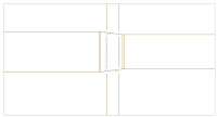
Post-script here....in some cases we have very tight clearances and the 3" duct height won't work. You can use a 1/4" diameter pipe and it will force the duct to hide under that as well. You might have to do one pipe over each side of the duct. Just a thought.
Draw a duct (doesn't matter what system you choose) that is an inch or two wider than the duct that is running underneath your transition, the smallest height possible (I think that is 3"), and only as long as the transition. Now select that duct and change its layer to your -Nplt layer. In elevation: you need to place this duct just underneath the transition, but above the duct that you want to show as hidden. You may have to go into an elevation view to make sure you get everything aligned. Once you have the elevation aligned you need to align it to be directly over the duct run you want to show hidden. You must make sure that your -Nplt layer is truly a non-plotting layer (verify in the layer manager that the print symbol has a red slash through it for this layer). Now go into paperspace and do a print preview and verify that you have hidden what you needed to, and nothing more. I have tested this out and it seems to work.
Here is an ortho view and a plan view of the results:


Post-script here....in some cases we have very tight clearances and the 3" duct height won't work. You can use a 1/4" diameter pipe and it will force the duct to hide under that as well. You might have to do one pipe over each side of the duct. Just a thought.
Tuesday, July 17, 2007
Duct Transition Not Hiding Duct Underneath
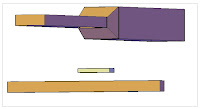
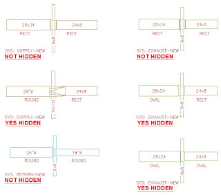
I have had quite the laundry list of items come up recently. One of them concerned duct transitions and how they were or were not hiding duct running underneath them. This is only for ductwork that is running horizontal in the top view. If you have a rect to rect or round to round transition (concentric or eccentric) and you have a duct running underneath it, the duct underneath will not hide. If you rotate it all 90 degrees it will appear hidden. If you have round to rect, oval to rect, or oval to oval it will appear hidden as well. Here is a screenshot.
(This is the first time I have posted any pics on my blog. Hopefully it'll turn out ok. :)

(This is the first time I have posted any pics on my blog. Hopefully it'll turn out ok. :)
Autodesk told me this is a known issue and it is fixed in MEP 2008. I do not believe we will be switching to 08 in the near future so my people need a solution for what is going on right now. Autodesk suggested exploding the transition and the duct running underneath and drawing in the required hidden lines....I'm not a fan of that idea. What I have told my people to do for the time being (other than just try to avoid this situation all together) is to use the "break" command on the duct running underneath and draw in some hidden lines where they need to appear in the transition area.
I just wanted to make others aware of this incase they run into it.
Good luck!
I just wanted to make others aware of this incase they run into it.
Good luck!
Flex duct: 1-line Representation
I just had one of the AUGI members ask how I got my flex duct to represent 1-line. I could have sworn that I had a blog post on this, but did not find one. So, here we go! :) I will preface this with: use a practice drawing first to try these changes out on first. You will need to verify that any changes that I am suggesting do not affect other settings in your drawings. Once you are pleased with the settings then you can set them in your existing and/or template drawings. We are using the MEP display configuration for all of our HVAC work at this time. You will need to make the changes to your display configuration that you have set for your ductwork drawings.
Hopefully this helps!
To get the flex duct to show as one line and to hide when it goes under other ducts/pipes follow this procedure:
When the label comes in for the flex duct the line runs thru it so you will have to erase the label for the flex duct after it is dropped in.
There is no known way to keep the label on for the rest of the ductwork and off for the flex duct. NOTE: the flex will not break/hide when it crosses more flex duct. Also once the flex duct is connected to a duct and to a "real" diffuser connector you can no longer manipulate the flex, you must move the diffuser or main duct and that will in turn relocate the flex.
We are using the MEP Design set as the display config.
Go to MODELSPACE to make these changes:
Format/Display manager/Sets/MEP Design-Plan
Scroll down to "Duct Flex" and check ONLY "Plan".
Format/Display manager/Representation by Object/Duct Flex/Plan
Turn everything OFF except "CL" and "CL Hidden"
Change the line types for CL to Hidden, and for CL Hidden to Hidden2
IF you wanted to have the label hide the line you can follow this procedure:
When using these settings the line will not hide when it goes under duct/piping. This is just in here for reference.
Go to MODELSPACE to make these changes:
Format/Display manager/Sets/MEP Design-Plan
Scroll down to "Duct Flex" and check ONLY "1-line".
Format/Display manager/Representation by Object/Duct Flex/1-line
Turn OFF "CL" and "Anno", keep everything else ON.
Change the line types for Contour to Hidden.
Friday, July 13, 2007
Parametric Parts
Greetings bloggers!
Here is what I have most currently learned. It is probably not the most correct method, but it produced what I was looking for. Here is the procedure that I went through to create a parametric part. I do not have all the options mapped out here because I have not fully investigated them. Happy reading!
Parametric Parts:
(Based off of creating a spin fitting)
Open up a blank drawing based off of your template.
Go to modelspace.
Go to CAD Manager/Content Editing/Content Builder
Select the chapter (folder) that you want to place your new part in.
(Make sure you are in the correct catalog…for parametric parts you will need to be in the duct or pipe catalog, not MvPart catalog)
Click on "New parametric part" icon on the right side.
Name your part. Hit tab to get to the next field. It should self-fill in.
Click "Ok".
Now a new palette will appear, the "content builder" palette.
Expand the "Part configuration" section.
You will see what you just named your part.
You can right click on it and select "edit" to change it if you would like.
Under that is the subcategory: "duct"
On "undefined" (under duct) right click and select "edit". Change it to "Takeoff".
Under the now named "takeoff" click on undefined and change it to "Plain" via right click/edit.
On the Content builder palette under the part config section is the "work plane" section.
Click on the "work plane" right click, and choose "edit".
Choose the desired plane--this is the plane that the object will be inserted/viewed initially in your dwg.
(when doing a spin fitting try the front plane)
Right click on the plane that you created.
Choose "Add geometry" then choose "line" (etc)
Add all the Cole lines that you need to through these functions.
You must use Cole lines in order for this to work.
You can not use regular ACAD lines/shapes.
Each asterisk is a Cole point = *
Once you have your item drawing you need to create and assign a profile to them.
Right click on your plane.
Select Add profile/circular (or whichever is applicable for you).
Draw this outside of the plane window.
Draw as required.
Create all desired planes.
These are basically giving a shape to extrude along.
Right click on your plane/add dimension/distance (or the desired one).
Dimension all portions that you want/need to control and reference.
Click on the *’s on your Cole lines.
Now assign a profile to the cole linework.
Under the Modeling section right click on "Modifier" and select "add path".
When it prompts you to "select path geometry", select the Cole points or Cole lines.
When it prompts you to "select start profile" choose the profile you had created.
It will then ask you to "select end profile" you can either choose a different that you need, or just hit enter to use the same as the start profile.
Do this for all of your Cole lines.
Right click on "Model Parameters".
Change any equations/relations that you need to.
Click in the equation column and make your changes.
You must type the variable names exactly as they have them listed.
Then click "close" when you are done.
Switch to a 3D view.
Right click on "Connections" and choose "Add connection".
Select the Cole Node that you want the connector located at.
Then enter a number for the connector.
For "Pick dimension position" prompt click on the profile that you drew that is outside the plane window.
Do this for all connections that you need.
Right click on "Parameter configuration" and choose "edit configuration".
Under the "Data storage" row change the items to "Table" that you want the people to choose from.
You must do this to the "Part size name" as well so you can edit the part names.
Now click the black down arrow at the top where it says "parameter configuration" and change it to "Values".
Click on the "1" row name.
A new icon is allowed at the top of this pop-up called "new".
Click on it as many times as you need to create choices to be chosen from.
You can click on the arrows with an "a" in the middle icon and this will auto-size your columns.
Now click inside the part size name to highlight the first name.
Click on the "edit" icon at the top left next to the "new" icon.
Change the name as required.
Use the down arrow keys and enter to change through all of these.
You must click on the "edit" button for each item you want to change.
Now click inside the other "list" items and change them accordingly.
Click "ok" to save the changes and exit this pop-up.
At the top of the content browser palette click on the cactus looking icon called "Generate bitmap".
Click on the views at the bottom of this pop-up and choose a view that suits you.
If you do not find something that you like, click on the "Browse" button and go find a bitmap to select instead.
Click on "Save part family" at the top of the content builder palette.
Click "yes" to allow this part to be seen by all users accessing it.
Click on the stoplight looking icon called "Validate".
Make sure you see a green dot at the bottom of the palette to signify that the part is valid.
Close the drawing.
It may prompt you to save, say YES.
Now double click on the catalog at the bottom of your ABS session.
Click on "d" for duct, or which ever catalog the part you just created is saved in.
Now you can test out your part!
To get to a newly created spin fitting that was stored in the duct catalog:
Click on "Duct fitting" icon on the palette.
Surf down to the location you saved it in, in this case:
Duct and fittings us imperial/round/takeoffs/
Click the down arrow to choose from the different sizes you created as choices and drop it into your drawing.
Subscribe to:
Posts (Atom)