Greetings bloggers...
Our company is still under-going the growing pains of an internet monitoring system.
I have unfortunately been unable to post. I hope to round up excellent information to post soon.
So sorry for the delay.
I did get to attend AU this year. It was the first time for me. It was amazing!!! I got to meet so many people and "celebrates" in the Autodesk, ACAD, ABS, ADT, Revit, etc worlds.
If Lynn Allen ever checks out this blog: "Hi! Your class on tips and tricks for Acad was amazing. I feel very privileged for having gotten to meet you."
Unfortunately, this is all I have time to post right now.
I hope everyone has a happy holiday season!!
Thursday, December 27, 2007
Monday, October 29, 2007
Happy Halloween!!!
Greetings fellow bloggers!
Unfortunately the internet blocks at work have not changed.
Therefore, I have been unable to post recently.
While you all wait for me to post important info, enjoy this site:
http://www.cubpack81.com/images/carve_pumpkin.swf
You can carve your own pumpkin w/o the mess!
Happy Halloween!!!
Unfortunately the internet blocks at work have not changed.
Therefore, I have been unable to post recently.
While you all wait for me to post important info, enjoy this site:
http://www.cubpack81.com/images/carve_pumpkin.swf
You can carve your own pumpkin w/o the mess!
Happy Halloween!!!
Tuesday, September 18, 2007
In the Works...
At the moment I am working on gathering more information on creating parametric parts.
I hope to get this information out there to you all soon.
Unfortunately, we are going through some "growing pains" and accessing/logging into my blogger account is a bit difficult at the moment. We hope to get this fixed soon...and/or I'll be moving my blog to a different website. If that is the case, I will post here to give you all the new link. Apparently too much "non-work oriented" material is hosted via blogger.com and it is on the "black list" of sites to be blocked.
Thank you for your patience!
Wednesday, August 15, 2007
AU 2007 Early Enrollment Open for AUGI Members
For those of you interested, the early enrollment for AU 2007 for AUGI members opened this morning. http://au.autodesk.com/
As I previously mentioned, you need to have an Autodesk user's login created.
If you don't it will ask you to do so at some point. (not sure when since I already had mine created)
Click on "AU 2007" at the top left hand side.
On the far right hand side there will be a button to "Register now" for AU.
Click on it.
You'll go through and do the registering for the actual event and hotel and then you will set up your classes. I discovered that I had to log out then log back in in order to access the class scheduler. B/t/w typically I have found you need to click on "lost password" and have them send you a new one at this point and log in w/ it, unless you want to wait quite awhile for some sort of confirmation email. (that's the only shortcut I've found).
The website is being bombarded. Be patient. Hit refresh OFTEN. There is no other way to register for this event. I even called the Autodesk University's help number: 1-888-371-1722 (8a-5p Pacific Time) to ask if there was another way. Nope. Just be patient. I do suggest you get signed up today if you can. The labs fill up fast!
Good luck and I hope everyone has a great time!
Thursday, August 09, 2007
Adding Duct Sizes to OOTB Size List
I thought I should post some information on how to add to the list of standard duct sizes that the duct pop-up allows you to choose from. Because I am only (at this time) making changes to the list of ductwork, not to all the fittings, it will ask for verification for creating a "custom" part .
Go to: Cad Manager/Content editing/Catalog editor
Go to File and Open the Duct US Imperial.apc catalog: ???
(depends on your server and filing system, most likely here) /enu/Aecb Catalogs/Duct US Imperial/
Expand the shape you want to work on (I did rectangular and then round)
Then expand Ducts/Rectangular duct/Constant lists
(For round: Duct/round duct/constants list)
Scroll down to the bottom, select a cell, and then hit enter on the last row items.
This will start a new row.
You have to do this for each individual cell, it does not just work for the entire row.
Once you have added and/or edited the sizes you want click on File/Save.
Then close out of the pop up.
Now double click on the catalog and regenerate the "duct" catalog.
You size changes/additions should immediately show up.
If not you can close out of ABS and get back into it and they should show up.
This is not tied to just one drawing, it should be accessible to all users with new and existing drawings.
Tuesday, August 07, 2007
AU Update
I just checked out Autodesk's AU info site.
It looks like general registration begins August 22, 2007.
Get it marked on your calendars!!
Be sure to stop by AUGI (Autodesk Users Group International) to get the low-down as well!
Create a free account at AUGI while you're there if you don't already have one.
AUGI: http://www.augi.com/home/default.asp
Wednesday, August 01, 2007
Autodesk University 2007
It's that time a year where we all line up chomping at the bit to sign up for AU!
For those of you who don't know what AU is...here's a link to Autodesk's website describing the event: http://www.autodeskevents.com/au2007/
It is a huge meeting of the minds where knowledge flows freely and new ways to tackle problems are found!
Registration starts soon!
For those of you who don't know what AU is...here's a link to Autodesk's website describing the event: http://www.autodeskevents.com/au2007/
It is a huge meeting of the minds where knowledge flows freely and new ways to tackle problems are found!
Registration starts soon!
Friday, July 20, 2007
BIM & PIM: Avatech White Paper
Congratulations to Mr. Brian Tuffin!!
He has posted an Avatech White Paper on BIM!
(the meer fact that he posted is almost as exciting as what he is posting, j/k Brian :)
Go check out his blog to read all about it: http://www.bim-wit.blogspot.com/
For those of you unfamiliar with BIM and PIM:
BIM = building information model
PIM = product information model
This is the way that designing and drafting is headed. You will no longer just be drafting lines on a drawing that symbolize items, you will actually be creating and utilizing intelligent objects. If you create a building information model through the usage of product information models the need for redesign and field issues are drastically diminished. All of the information is at your fingertips. Manufacturers need to get in on this! The sooner they create PIM's of their products the more designers will want to use their products.
Wednesday, July 18, 2007
Update on Duct under Transition Hiding Issue
I received another option from Autodesk concerning the duct under a transition not hiding. I liked this idea and thought you all should know about it as well.
Draw a duct (doesn't matter what system you choose) that is an inch or two wider than the duct that is running underneath your transition, the smallest height possible (I think that is 3"), and only as long as the transition. Now select that duct and change its layer to your -Nplt layer. In elevation: you need to place this duct just underneath the transition, but above the duct that you want to show as hidden. You may have to go into an elevation view to make sure you get everything aligned. Once you have the elevation aligned you need to align it to be directly over the duct run you want to show hidden. You must make sure that your -Nplt layer is truly a non-plotting layer (verify in the layer manager that the print symbol has a red slash through it for this layer). Now go into paperspace and do a print preview and verify that you have hidden what you needed to, and nothing more. I have tested this out and it seems to work.
Here is an ortho view and a plan view of the results:
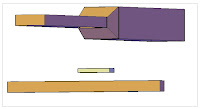
Post-script here....in some cases we have very tight clearances and the 3" duct height won't work. You can use a 1/4" diameter pipe and it will force the duct to hide under that as well. You might have to do one pipe over each side of the duct. Just a thought.
Draw a duct (doesn't matter what system you choose) that is an inch or two wider than the duct that is running underneath your transition, the smallest height possible (I think that is 3"), and only as long as the transition. Now select that duct and change its layer to your -Nplt layer. In elevation: you need to place this duct just underneath the transition, but above the duct that you want to show as hidden. You may have to go into an elevation view to make sure you get everything aligned. Once you have the elevation aligned you need to align it to be directly over the duct run you want to show hidden. You must make sure that your -Nplt layer is truly a non-plotting layer (verify in the layer manager that the print symbol has a red slash through it for this layer). Now go into paperspace and do a print preview and verify that you have hidden what you needed to, and nothing more. I have tested this out and it seems to work.
Here is an ortho view and a plan view of the results:


Post-script here....in some cases we have very tight clearances and the 3" duct height won't work. You can use a 1/4" diameter pipe and it will force the duct to hide under that as well. You might have to do one pipe over each side of the duct. Just a thought.
Tuesday, July 17, 2007
Duct Transition Not Hiding Duct Underneath
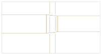
I have had quite the laundry list of items come up recently. One of them concerned duct transitions and how they were or were not hiding duct running underneath them. This is only for ductwork that is running horizontal in the top view. If you have a rect to rect or round to round transition (concentric or eccentric) and you have a duct running underneath it, the duct underneath will not hide. If you rotate it all 90 degrees it will appear hidden. If you have round to rect, oval to rect, or oval to oval it will appear hidden as well. Here is a screenshot.
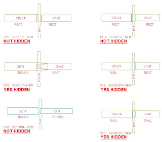
(This is the first time I have posted any pics on my blog. Hopefully it'll turn out ok. :)

(This is the first time I have posted any pics on my blog. Hopefully it'll turn out ok. :)
Autodesk told me this is a known issue and it is fixed in MEP 2008. I do not believe we will be switching to 08 in the near future so my people need a solution for what is going on right now. Autodesk suggested exploding the transition and the duct running underneath and drawing in the required hidden lines....I'm not a fan of that idea. What I have told my people to do for the time being (other than just try to avoid this situation all together) is to use the "break" command on the duct running underneath and draw in some hidden lines where they need to appear in the transition area.
I just wanted to make others aware of this incase they run into it.
Good luck!
I just wanted to make others aware of this incase they run into it.
Good luck!
Flex duct: 1-line Representation
I just had one of the AUGI members ask how I got my flex duct to represent 1-line. I could have sworn that I had a blog post on this, but did not find one. So, here we go! :) I will preface this with: use a practice drawing first to try these changes out on first. You will need to verify that any changes that I am suggesting do not affect other settings in your drawings. Once you are pleased with the settings then you can set them in your existing and/or template drawings. We are using the MEP display configuration for all of our HVAC work at this time. You will need to make the changes to your display configuration that you have set for your ductwork drawings.
Hopefully this helps!
To get the flex duct to show as one line and to hide when it goes under other ducts/pipes follow this procedure:
When the label comes in for the flex duct the line runs thru it so you will have to erase the label for the flex duct after it is dropped in.
There is no known way to keep the label on for the rest of the ductwork and off for the flex duct. NOTE: the flex will not break/hide when it crosses more flex duct. Also once the flex duct is connected to a duct and to a "real" diffuser connector you can no longer manipulate the flex, you must move the diffuser or main duct and that will in turn relocate the flex.
We are using the MEP Design set as the display config.
Go to MODELSPACE to make these changes:
Format/Display manager/Sets/MEP Design-Plan
Scroll down to "Duct Flex" and check ONLY "Plan".
Format/Display manager/Representation by Object/Duct Flex/Plan
Turn everything OFF except "CL" and "CL Hidden"
Change the line types for CL to Hidden, and for CL Hidden to Hidden2
IF you wanted to have the label hide the line you can follow this procedure:
When using these settings the line will not hide when it goes under duct/piping. This is just in here for reference.
Go to MODELSPACE to make these changes:
Format/Display manager/Sets/MEP Design-Plan
Scroll down to "Duct Flex" and check ONLY "1-line".
Format/Display manager/Representation by Object/Duct Flex/1-line
Turn OFF "CL" and "Anno", keep everything else ON.
Change the line types for Contour to Hidden.
Friday, July 13, 2007
Parametric Parts
Greetings bloggers!
Here is what I have most currently learned. It is probably not the most correct method, but it produced what I was looking for. Here is the procedure that I went through to create a parametric part. I do not have all the options mapped out here because I have not fully investigated them. Happy reading!
Parametric Parts:
(Based off of creating a spin fitting)
Open up a blank drawing based off of your template.
Go to modelspace.
Go to CAD Manager/Content Editing/Content Builder
Select the chapter (folder) that you want to place your new part in.
(Make sure you are in the correct catalog…for parametric parts you will need to be in the duct or pipe catalog, not MvPart catalog)
Click on "New parametric part" icon on the right side.
Name your part. Hit tab to get to the next field. It should self-fill in.
Click "Ok".
Now a new palette will appear, the "content builder" palette.
Expand the "Part configuration" section.
You will see what you just named your part.
You can right click on it and select "edit" to change it if you would like.
Under that is the subcategory: "duct"
On "undefined" (under duct) right click and select "edit". Change it to "Takeoff".
Under the now named "takeoff" click on undefined and change it to "Plain" via right click/edit.
On the Content builder palette under the part config section is the "work plane" section.
Click on the "work plane" right click, and choose "edit".
Choose the desired plane--this is the plane that the object will be inserted/viewed initially in your dwg.
(when doing a spin fitting try the front plane)
Right click on the plane that you created.
Choose "Add geometry" then choose "line" (etc)
Add all the Cole lines that you need to through these functions.
You must use Cole lines in order for this to work.
You can not use regular ACAD lines/shapes.
Each asterisk is a Cole point = *
Once you have your item drawing you need to create and assign a profile to them.
Right click on your plane.
Select Add profile/circular (or whichever is applicable for you).
Draw this outside of the plane window.
Draw as required.
Create all desired planes.
These are basically giving a shape to extrude along.
Right click on your plane/add dimension/distance (or the desired one).
Dimension all portions that you want/need to control and reference.
Click on the *’s on your Cole lines.
Now assign a profile to the cole linework.
Under the Modeling section right click on "Modifier" and select "add path".
When it prompts you to "select path geometry", select the Cole points or Cole lines.
When it prompts you to "select start profile" choose the profile you had created.
It will then ask you to "select end profile" you can either choose a different that you need, or just hit enter to use the same as the start profile.
Do this for all of your Cole lines.
Right click on "Model Parameters".
Change any equations/relations that you need to.
Click in the equation column and make your changes.
You must type the variable names exactly as they have them listed.
Then click "close" when you are done.
Switch to a 3D view.
Right click on "Connections" and choose "Add connection".
Select the Cole Node that you want the connector located at.
Then enter a number for the connector.
For "Pick dimension position" prompt click on the profile that you drew that is outside the plane window.
Do this for all connections that you need.
Right click on "Parameter configuration" and choose "edit configuration".
Under the "Data storage" row change the items to "Table" that you want the people to choose from.
You must do this to the "Part size name" as well so you can edit the part names.
Now click the black down arrow at the top where it says "parameter configuration" and change it to "Values".
Click on the "1" row name.
A new icon is allowed at the top of this pop-up called "new".
Click on it as many times as you need to create choices to be chosen from.
You can click on the arrows with an "a" in the middle icon and this will auto-size your columns.
Now click inside the part size name to highlight the first name.
Click on the "edit" icon at the top left next to the "new" icon.
Change the name as required.
Use the down arrow keys and enter to change through all of these.
You must click on the "edit" button for each item you want to change.
Now click inside the other "list" items and change them accordingly.
Click "ok" to save the changes and exit this pop-up.
At the top of the content browser palette click on the cactus looking icon called "Generate bitmap".
Click on the views at the bottom of this pop-up and choose a view that suits you.
If you do not find something that you like, click on the "Browse" button and go find a bitmap to select instead.
Click on "Save part family" at the top of the content builder palette.
Click "yes" to allow this part to be seen by all users accessing it.
Click on the stoplight looking icon called "Validate".
Make sure you see a green dot at the bottom of the palette to signify that the part is valid.
Close the drawing.
It may prompt you to save, say YES.
Now double click on the catalog at the bottom of your ABS session.
Click on "d" for duct, or which ever catalog the part you just created is saved in.
Now you can test out your part!
To get to a newly created spin fitting that was stored in the duct catalog:
Click on "Duct fitting" icon on the palette.
Surf down to the location you saved it in, in this case:
Duct and fittings us imperial/round/takeoffs/
Click the down arrow to choose from the different sizes you created as choices and drop it into your drawing.
Friday, June 29, 2007
Missing Curve/End Coonector and Osnap Symbols?
So I had been hoping to get more posts out here quicker. Unfortunately, other tasks at work have kept me away from reviewing and posting some of the information I had learned at class.
Right now I am dealing with my wipeout blocks showing up correctly in modelspace and paperspace, but when you print and/or do a print preview they don't hide the stuff underneath them. This is quite frankly annoying. I am using them to place text on top of 1-line piping. If anyone has any suggestions please feel free to drop a comment. This used to work...now it's stopped working. I just can't figure out why. It's not computer, drawing, or printer specific. I think I may have messed up some setting in my template and I can't figure out which one. I've gone through my notes and "un-did" those changes...it still doesn't work any more. WHY?! Sigh. Maybe I'll post this on AUGI and/or the Autodesk Subscription Center.
Today I had an interesting question...a user's osnap and end/curve connector symbols were not showing up. The pop-up text stating that you were on a curve connector (etc) did show up so we knew it was working, just not visual. here's how to fix this in case any of you run across this same problem.
Right click on the "osnap" button at the bottom and choose "settings".
Make sure you are in either the Osnap tab or the ABS Snap tab.
Click on the "Options" button.
You will now be in the options pop-up.
Make sure you are on the "Drafting" tab.
Under the "AutoSnap Settings" section make sure "Marker" is check marked.
Also I keep "magnet" and "display autosnap tooltip" checked as well.
Click "Ok" once you are done here.
You will be back in the Drafting settings pop-up.
Click "Ok".
Wednesday, June 06, 2007
Cut Plane
Good afternoon all,
So sorry it has been quite awhile since I have gotten to post. I have been swamped after coming back from my training. I am attempting to get caught up so that I can dig in and start "fixing" and amending my set-up for my dept. It's quite a task ahead of me and many choices to make.
In the process I have had a couple of people telling me that when they xref in a structural drawing to look at the steel for their floor, they can't see it. Everything is turned on, but no steel.
It turns out that when I decided to use the OOTB cut plane for my display configuration it ended up cutting off before the steel showed up.
Anyway...enjoy the info listed below and hopefully I can get more posts out quicker in the coming days!
So, here's how to change your cut plane elevations:
Open up your template.
Go to modelspace.
Go to Format/Display Manager/Configurations/
Now choose the display configuration that you need to change the cut plane on.
For me it is "MEP Design".
Click once on it to select it.
In the right hand column click on the "Cut Plane" tab.
Here are the settings that I am going to use:
Display above range: 200'-0" (yes, this is huge, but if you knew how our dwgs were set-up, it would make more sense)
Cut height: 3'-6" (didn't change this one)
Display below range: 0" (didn't change this one)
Thursday, May 10, 2007
Helpful Hints:Isolate Objs, Commands, & Cont Browser
Here are a couple helpful hints I picked up in training, enjoy!
When you want to see just a few objects in 3D and modify/add/delete from them:
Select the objects you want to see.
Right click.
Select "isolate objects"
Choose either edit in section, plan, or elevation.
Follow the command line prompts to cut the section or elevation.
Now your objects will pop-up in a separate window.
You can add objects (pipe, duct, equipment, aec content) or modify objects as desired here.
Once you are done, click on the "edit in view" pop-up toolbar button to exit this window.
Command line commands:
You can type in the first letter or two and then hit tab and it will tab you through all of the commands that are available with those letters.
Keep in mind the duct and pipe commands are actually "add duct" and "add pipe" so it will not be under "d" for duct or "p" for pipe, it will be under "a" for add.
If you want to see all the available commands used in ABS: at the command line type "arx" then choose "c" for commands.
Content Browser: If you want to keep this window on top all the time:
Open the content browser.
Right click on the top of its title bar and choose "Always on top".
Wednesday, May 02, 2007
In the works...
I am currently undergoing quite the educational gauntlet. Hopefully soon I will have many more new tidbits to bring to light here on my blog once I return.
It has been quite an exciting and informational little sabbatical.
I want to give a big thank you out to my trainer!! :)
Keep this site handy...as soon as I can decipher my notes I'll throw some tidbits out here.
It has been quite an exciting and informational little sabbatical.
I want to give a big thank you out to my trainer!! :)
Keep this site handy...as soon as I can decipher my notes I'll throw some tidbits out here.
Friday, April 20, 2007
Selection Windows
Good morning,
I was reading some material concerning ACAD 2007 and wondered if it worked in ABS 2007. The answer is "yes it does!" I thought these little tricks were fun so I wanted to pass them off to you all.
Selection Windows
Implied window: Go from left to right (up or down, doesn’t matter). Shows a solid line, enclosed items are selected.
At the "select objects" prompt type "W" and left to right doesn’t matter either.
Implied crossing window: Go from right to left (up or down, doesn’t matter). Shows dashed line, all items touched by the window are selected.
At the "select objects" prompt type "C" and right to left doesn’t matter either.
For either type of window:
At the "select objects" prompt type "WP" for window polygon.
At the "select objects" prompt type "CP" for crossing polygon.
At the "select objects" prompt type "F" for fence selection. (anything it crosses is selected)
Thursday, April 19, 2007
Good Luck!
Greetings Blog Readers,
Today is one of my co-workers last day here at work. He has been a tremendous help in setting up the ADT side of things. He will definitely be missed. He's probably one of the main reasons I've stayed partially sane ;)
I wish him the best of luck at his new job! I know he will do well.
(Hopefully he'll hang in and still play on the coed softball team with us this summer!)
Good luck!!
Tuesday, April 10, 2007
.CTB's: Create, Edit, Map, & Convert
Good morning Bloggers!
I thought I would drop some information in concerning .ctb files. At my company we print based off of the .ctb as opposed to the .stb. Just as an explination: a ctb file is a color table. When a .ctb is utilized to print the lineweights are based off of the color. A .stb is a style based pen table. When you are using a .stb the lineweights are based off of the lineweight of the actual line, the color is irrelevant.
To create a new .ctb:
Go to C:\Documents & Settings\all users\Autodesk\ABS\enu\Plot styles
Copy the one you want to use as a template that has most of your layer keys loaded
Rename the copy you made
Double click and open it
This can be edited in either the form view or the table view
Screening = shading percent value (set all colors to 100%, set the shades to the % required)
Make sure if you are making a .ctb file that the "color" row is set to black instead of "use object color"
Also you can get to this via the control panel/autodesk plot style manager.
To edit a .ctb file:
Go to Windows Explorer.
Open this file: F:\HBEDT2k6\Plot Styles\HBE ADT-ABS.ctb
Click on the View tab.
Edit as required.
Click on the Save and Close button.
To map new a .ctb to ABS:
The new .ctb is here: F:\HBEDT2k6\Plot Styles\HBE ABS.ctb
You have to load this into your profile in order for it to apply to everyone.
To convert a .stb drawing to a .ctb drawing:
Once your drawing is started as a .stb you will not be able to print it properly using our .ctb file.
To convert it: type "convertpstyles" in the command line.
Set pstylemode = 0 ( for color dependent/.ctb mode)
It will give you a warning, say OK.
Thursday, April 05, 2007
Follow-up: Obj Inspect/Autosnap
Good afternoon all,
I thought I would post some follow-up information concerning the object inspect tool and the autosnap setting.
To check and/or change your autosnap value setting type "autosnap" at the command prompt.
"Enter new value for AUTOSNAP <#>:" will appear at the command line, where the "#" is an actual number dependent upon your settings. To change the value simply type in the new numeric value and hit enter.
R. Robert Bell passed me this information on the Autodesk Discussion Group concerning how the autosnap value gets changed (http://discussion.autodesk.com/thread.jspa?threadID=551907):
"That value changes depending on what settings they've applied in the Options dialog, or on the Status bar. The value of that system variable is a total of the bit codes being set. If you don't know what bit codes are, you aren't a programmer. ;^) Only values from 0-63 will be valid in current releases. Attempts to set it to other values will either be ignored or refused."
He also posted this: "Bit 1 (value 2) is what you need on to see the tooltip. So add this to AcadDoc.lsp or your CUI's .mnl file: (setvar "AutoSnap" (boole 7 (getvar "AutoSnap") 2)) "
On AUGI I had this thread going to discuss autosnap values as well: http://forums.augi.com/showthread.php?t=57359
David Koch posted this explanation for me: "The variable is binary bit-coded so that a number of different "on-off" settings can be stored in one variable. Base 2 [binary] has two possibilities for each digit - 0 [off] or 1 [on]. With a computer, it is easy to test if a given bit is set, even if it not not terribly obvious when the number is converted to a Base 10 [decimal] number, like we are used to seeing.
0 turns off everything, as that means all bits are off.The zero bit [two raised to the zero power] is 1 when on, and turns on the AutoSnap marker.
The two's bit [two raised to the first power] is 2 when on [10 in binary], and turns on the AutoSnap tooltips.
So, 3 [11 in binary] means that both the AutoSnap marker and the AutoSnap tooltips are turned on.
The four's bit [two raised to the second power] is 4 when on [100 in binary], and turns on the AutoSnap magnet.
So, 5 [101 in binary] means that the AutoSnap marker and the AutoSnap magnet are on, and everything else is off. 6 [110] means that the AutoSnap tooltips and the AutoSnap magnet are on; 7 [111] means all of the above are on.
That carries on for each of the remaining bits:
Eight's bit [two to the third power] turns on polar tracking when set.
16's bit [two to the fourth power] turns on object snap tracking when set.
32's bit [two to the fifth power] turns on tooltips for polar tracking, object snap tracking, and Ortho mode.
From what you have posted, and as Scott mentioned, the 32 bit appears to be the magic one. Any number between 32 and 63 has the 32 bit set, so any value greater than that would support the object inspect tool tip. Besides setting the value directly in the system variable, turning polar tracking or object snap tracking on or off on the Application Status Bar, or changing any of the AutoSnap settings in the Options dialog, etc, would result in a change to the value.
If you really wanted to force this to be on, someone wiser than I with regard to the proper construction of reactor programs could help you devise one that would automatically check the value of AUTOSNAP and, if the 32 bit was not set, set it. That would still allow your users to set the other bit values as needed, and only force the display of the tooltips controlled by the 32 bit."
So there ya go folks...all the info I could round up for the time being. Hopefully this will help some of you out.
Wednesday, April 04, 2007
Remapping a Layer for an Individual Object
Good afternoon all!
I was going through my notes and discovered that I had not posted this little diddy.
Enjoy!
Remapping a Layer for an Individual Object:
(This will load in a standard layer with all of its proper settings, even if the layer is not already in the drawing)
Go to the Format drop down menu.
Select "Layer Manager".
Select "Remap Object Layers".
Select the object or objects you want to change to one different layer.
Hit enter.
At the command line prompt it will ask for the Layer Key.
Either type in the layer key if you know it and hit enter,
OR type in a "?" and hit enter.
If you pull the command line window up you will be able to see all the layer keys that are possible and you can scroll through them.
You can either write down the layer key you need and type it back in
OR you can hold down the left click button to highlight the layer key you want, then hit the right click button and select copy.
Then left click once at the command line (to get the cursor back down there).
Now right click and select paste to drop in the layer key name you copied from the list above.
Hit enter.
Friday, March 23, 2007
Dimensions: Modification of Text Output
Good morning bloggers!
Here is just a helpful tip...some of you may know this already, but some of you may not. I come from the old school of learning that involved typing commands. I remembered there was a way to force a dimension to enter to the next line thereby creating 2 lines of text for a dimension. Since I began my ABS path I have not had to do 2 lines or more of dimension text. It turns out that "\X" still works, however I had the unique situation of needing 3 lines of text. To get this I learned that you type in "\P" at each point that you want a new line created. Here is the more specific run through of how to modify and create multiple lines of text in a dimension. Keep in mind if you are wanting to keep the dimension that is measured type this in: "<>". By the way, the capitalization of the "P" and the "X" is important.
Dimensions: Modification of Text Output:
If you want to modify the information that is in a dimension click once on the dimension to select it.
Go to the Properties palette.
Scroll down to the "Text" section.
Under "Text override" you can type in anything you want.
If you need 2 lines you can type in the information for the first line then type "\X" and then type in the next line.
If you need more than 2 lines, type in the info for the first line then type "\P" at the beginning of each new line.
You can use the "\P" for a double line as well if you would like instead of the "\X".
Then just hit "enter" once you have everything typed in there.
You may have to hit "esc" to unselect your dimension text.
You may need to move/align your dimension text.
Monday, March 19, 2007
Eccentric Duct Transitions & Round Taps (Not Shoe/Beveled)
As I have mentioned my company has a set of standard ways they want to see their ductwork represented. OOTB the ductwork drops in with concentric (centered) fittings, our company uses eccentric. Also OOTB shoe-taps/beveled taps show up automatically for round duct. Our company likes to use spin fittings. While I have not found an acceptable spin fitting in the catalog yet, for the time being I have chosen to change the fitting that is automatically dropped in to a round duct straight tap. This way my people can just draw a line to represent the other portion of the spin fitting symbol we typically use until I can create one. I have listed below the steps that I took to accomplish these settings.
For Round Duct:
Click on the "Add duct" button on the Duct palette.
Choose Round duct.
Under Justification set Horizontal to "Left", keep Vertical set to "Center".
Go to the black down arrow at the bottom of this pop-up and click it once and WAIT.
Under "Takeoff" make sure "Round duct take off US imperial" is checked.
Under "Transition" make sure "Eccentric round duct transition US imperial" is checked.
Then draw a couple of ducts to make sure this setting stuck.
For Rectangular Duct:
Click on the "Add duct" button on the Duct palette.
Choose a Rectangular duct.
Under Justification set Horizontal to "Left", keep Vertical set to "Center".
Go to the black down arrow at the bottom of this pop-up and click it once and WAIT.
Under "Takeoff" make sure "Rectangular duct take beveled tap US imperial" is checked.
Under "Transition" make sure "Rectangular duct eccentric transition US imperial" is checked.
Then draw a couple of ducts to make sure this setting stuck.
Wednesday, March 14, 2007
Object Inspect Tool & Autosnap Setting
The object inspect tool a great tool, if you can get it to work. I have been challenged recently to get this to work. Here is what has been going on. On some people’s computers it works, on others it does not. It could be working on someone’s computer for awhile and then just quit working. It is independent of the profile, the template, and whether or not you are using ABS 2007 or ADT 2007. Due to those tests that I ran I had a hunch it was a system variable or some toggle somewhere under the Options/Drafting tab, aka it was specific to the individual computer.
What I mean by not working: you could select the object inspect tool and hover over an item, but no text balloon would show up with the information, but the command was active.
Thanks to some help from the people on AUGI I have found out what the toggle/system variable is that affects it. AUTOSNAP. This was a variable that I had never heard of. OOTB it should be set to 63.
From the help section here are the settings for Autosnap: 0 = Off all, 1 = marker on, 2 = snap tip on, 4 = magnetic cursor on, 8 = polar tracking on, 16 = object snap tracking on, and 32 = tool tips for polar and object snap tracking on.
Now if you add all of these together (0+1+2+4+8+16+32) it equals 63. Interesting.
I went around to various computers and found these numbers for autosnap: 1, 5, 17, 39, 47, and 55. I know that my users do not know about this system variable, nor do they know how to directly change it’s setting. Interestingly enough anyone who had a number above and including 30 the object inspect tool worked on their computers.
If you turn on and off items such as osnap or otrack the autosnap value will change.
So how do you insure that you always have a high enough number for your autosnap setting in order to keep the object inspect tool working? I just don’t know yet. I’ll update this post with new information when I find out!
Also just to note…I verified that in the Options/Drafting tab the following were all checked/selected: Marker, Magnet, and Display Autosnap tool tip.
Friday, March 09, 2007
File extension Names
So if you are new to customizing a CAD system and you are just learning the ropes there are some basic file extension names that you will want to know what they are used for. I have put together a small list and their "definitions" that I have found handy.
File Extensions and What They Mean:
.dsd = batch plot sheet set listing, holds the sheet names to access
.dwf = image of a drawing, does not update when drawing updates
.dwg = drawing
.dwt = template, used to create your new drawings with the settings previously configured
.exe = executable file, can be used for a self-extracting zip file
.pdf = image file, non-editable by CAD, typically used with Adobe
.txt = text file
.zip = zip file
Thursday, March 01, 2007
Turning Off Pipe Fitting Connectors
If your company is very specific on what can or can't be shown on your drawings some of the OOTB features for ABS are not desired. One of these particular items for my company is the connectors on pipe fittings for 1-line representation. Here is how to turn those off. Rest assured that the rise/drop/tee fittings still show up, this is just the connectors that come before/after the fitting.
Open up your template drawing.
This will take care of all future issues started off of the template, but you will have to open up any existing individual drawings and amend these settings as well.
Go to modelspace.
Go to Format/Display Manager/Representation by Object/Pipe fitting/
In my case the Display configuration I always use for piping is "Plan", so I will select "Plan".
Turn OFF the "connector", "connector-graphical", and "connector-hidden".
Also you may need to go under /Representation by Object/Pipe custom fitting/ as well.
Turn OFF the "connector", "connector-graphical", and "connector-hidden" here also.
Click "Apply" and then click "OK".
You may need to tweak this for your situation, but now you know where those pesky connectors are so you can turn them off if you need to.
Wednesday, February 28, 2007
1-line Pipe Rise/Drop Representation
As I continue to try to implement ABS 2007 there are things I hear about every day. This one I had to tap one of my "sources" (big shout out of thanks to my favorite "Pepper") to get me on the right track.
We were wanting to get the 1-line piping's rise and drop symbols to be "legible" at all times, no matter if it's a 3/4" dia or 6" dia pipe. OOTB it appears the the symbols scale with the size of the pipe.
So, you all can learn from my challenges....
Open up your template drawing.
(this will take care of future drawings, but you will have to go into your already created drawings and modify this there as well.)
Go to modelspace.
Click on "Format", and then "Style Manager".
You will see your template drawing listed there: Template.dwt (or whatever the drawing name)
Surf down "Piping Objects"/"Pipe rise drop symbols".
Since my pipes are set to use the "Pipe break-rise only" I will modify this one.
You will need to modify whichever one your pipes are affected by.
Click on the "Rise/Drop" tab.
Here is what I had to modify to show 10" dia symbols at all times:
Circular drop 1-line: under scale click on "Override scale", input: x=10, y=10, z=1
Circular rise 1-line: under scale click on "Override scale", input: x=10, y=10, z=10
Circular drop 1-line tee: left alone for now.
Anyway, that's where I stand at the moment, and it seems to be working...I'll know for sure in a couple of weeks!
Wednesday, February 14, 2007
Happy Valentine's Day
Here's wishing you all a Happy Valentine's Day!
For all of you getting dumped on w/ snow: don't let it damper your day.
Just make some creative snowpeople!
For some "mindless" fun try this link out: http://blackdog4kids.com/holiday/valentine/tictactoe/
For all of you getting dumped on w/ snow: don't let it damper your day.
Just make some creative snowpeople!
For some "mindless" fun try this link out: http://blackdog4kids.com/holiday/valentine/tictactoe/
Wednesday, January 31, 2007
Placing Nodes (may be desired for MvParts)
When creating MvParts you may want to place some nodes to hold a place for your connectors. It is not a requirement, but can come in handy. Here's a quick reference on customizing the output of your nodes.
Placing Nodes:
Node Point: type "po" at the command line
DdPType: displays a dialog box for selecting PsMode and PdSize
PDMODE choices and what they deliver: 0=dot, 1=invisible, 2=+, 3=x, 4='
32-36 is the same as 0-4 w/ a circle around them
64-68 is the same as 0-4 w/ a square around them
96-100 is the same as 0-4 w/ a square and then a circle around them.
PDSIZE choices and what they deliver: 0=5% of height of the ScreenSize system variable
1=No display
-10=(Negative) 10% of the viewport size
10=(Positive) 10 pixels in size
Wednesday, January 17, 2007
MvPart: Modifying Layer Keys in Content Builder
In honor of attempting to help you all keep your New Year's resolution of continuing education
here is the next tid-bit I have to offer up to you all. Ah, the joys of MvParts. It's a never ending pool of discovery...enjoy!
MvPart: Modifying the Layer Keys in Content Builder:
Once you have the views modified the way you want them you may want to modify the layer keys that the blocks are set to.
This must be done in the Content Builder.
Open a blank drawing based off of your template, make sure you have the desired layer key loaded in this drawing.
Make sure you are in modelspace.
Make sure you have Regenerated the Catalog first.
Go to the CAD Manager/Content Editing/Content Builder/Part Catalog and choose Multi-view Part.
Catalog path: ...\enu\Aecb Catalogs\MvParts US Imperial\Mechanical\Mechanical\All
Installed MvParts US Imperial.apc
Surf down: All Installed MvParts US Imperial/Mechanical/Air Terminals/Diffusers
Select the one you want to work on.
Then click on the "modify part size" button that is on the right hand side, approximately the 5th one down.
In the layer key area click on the ellipse "…" button.
Select your layer key; the layer key used is the one associated w/ your open drawing.
NOTE: You can not type in layer keys, you have to select one.
Click "ok" to exit this window.
Click "ok" to exit out of the Content Builder.
You will have to regenerate the catalog (m = mvpart) after making these changes.
In order for everyone to see your changes both you and everyone else will have to exit out of ABS completely.
Then open ABS back up and they should be able to view your changes.
Tuesday, January 02, 2007
Happy New Year
Happy New Year!!!
Remember, when making resolutions be sure they are attainable ones. You sure don't want to start out the new year by not accomplishing something. Try something like..."This year I will learn a new function of ABS 2007." :) You know you can accomplish this by just reading my blog! See, I'm here to help.
Hope you all have a Happy New Year!
Subscribe to:
Posts (Atom)